Cleanroom Certification & Testing
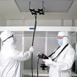
ISO Class 1-9 cleanrooms are required per ISO 14644-2:2015 to be certified at a minimum time interval of once per year. ACM™s certified technicians follow ISO procedural standards and serve the Medical Device, Pharma, Aerospace and Semiconductor industries. ACM will perform Cleanroom Certification and Testing for FFU’s, Biological Safety Cabinets (BSC), fumehoods, laminar flowbenches, and isolators.
Trust your cleanroom to the experts in the business, contact us and speak to our engineer for a consultation on how ACM can best help with your cleanroom certification and testing needs.
Primary Certification Tests Include:
- Airflow volume / velocity readings with room air exchange rate calculations
- Filter challenge / ambient air
- Filter challenge / aerosol (PAO or PSL)
- Room pressure differential measurements
- HEPA filter integrity test
- Non-viable particle counting
- Temperature / relative humidity measurements
Other Services Include:
- Room recovery
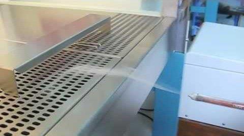
- Air laminarity visualization test
- Filter leak repair
- Filter replacement
- ESD surface conductivity testing
- Molecular air and surface testing
- Lighting, vibration, and noise tests
- Viable Air and Surface Sampling with Total Numerology or Gram Stain results


1.1 Airborne Particle Count
PURPOSE: To measure the particle levels in the cleanroom in order to classify the room.
INSTRUMENTATION: Particle Counter – Calibration documents on equipment used for certification are attached to the report.
PROCEDURES: Divide the Cleanroom work zone into grids of equal proportion and plot the sample locations according to room class and standard used to classify the cleanroom. Place the particle counter probe and take samples perpendicular to the airflow at working height. Record and report data for each considered particle size for the designated classification.
ACCEPTANCE: The average particle concentration at each sample location should fall at or below class limit, and the mean of these averages should fall at or below the class limit. Under certain circumstances a 95% confidence limit is computed.
1.2 Airborne Particulate Cleanliness Classes
ISO 14644-1
| CLASS | 0.1 MICRON | 0.2 MICRON | 0.3 MICRON | 0.5 MICRON | 1.0 MICRON | 5.0 MICRONS |
| ISO 1 | 10 | 2 | – | – | – | – |
| ISO 2 | 100 | 24 | 10 | 4 | – | – |
| ISO 3 | 1,000 | 237 | 102 | 35 | 8 | – |
| ISO 4 | 10,000 | 2,370 | 1,020 | 352 | 83 | – |
| ISO 5 | 100,000 | 23,700 | 10,200 | 3,520 | 832 | 29 |
| ISO 6 | 1,000,000 | 237,000 | 102,000 | 35,200 | 8,320 | 293 |
| ISO 7 | – | – | – | 352,000 | 83,200 | 2,930 |
| ISO 8 | – | – | – | 3,520,000 | 832,000 | 29,300 |
| ISO 9 | – | – | – | 35,200,000 | 8,320,000 | 293,000 |
Federal Standard 209E
| CLASS | 0.1 MICRON | 0.2 MICRON | 0.3 MICRON | 0.5 MICRON | 1.0 MICRON | 5.0 MICRONS |
| 1 | 35 | 7.5 | 3 | 1 | – | – |
| 10 | 350 | 75 | 30 | 10 | – | – |
| 100 | – | 750 | 300 | 100 | – | – |
| 1,000 | – | – | – | 1,000 | – | 7 |
| 10,000 | – | – | – | 10,000 | – | 70 |
| 100,000 | – | – | – | 100,000 | – | 700 |
Conversion Table
|
Particle Counts / ft3 (> 0.5 mm) |
Federal Standard209 E Class |
Particle Counts / m3 (> 0.5 mm) |
New ISO 14644-1 Class |
| 32,200,000 | ISO Class 9 | ||
| 100,000 | Class 100,000 | 3,520,000 | ISO Class 8 |
| 10,000 | Class 10,000 | 352,000 | ISO Class 7 |
| 1,000 | Class 1,000 | 35,200 | ISO Class 6 |
| 100 | Class 100 | 3,520 | ISO Class 5 |
| 10 | Class 10 | 352 | ISO Class 4 |
| 1 | Class 1 | 35 | ISO Class 3 |
| 4 | ISO Class 2 | ||
| ISO Class 1 |
AVERAGE, MEAN, STANDARD DEVIATION, STANDARD ERROR AND UPPER CONFIDENCE LIMITS (UCL):
FOR ROOMS WHERE NUMBER OF SAMPLING LOCATIONS IS MORE THAN ONE AND LESS THAN NINE
AVERAGE PARTICLE CONCENTRATION:
| C1 + C2 + … + CN | ||
|
N |
||
A= Where C1, C2,……, CN = Individual particle counts
N = Number of particle counts taken at each location.
MEAN OF AVERAGES:
| A1 + A2 + … AN | ||
|
L |
||
M = Where A1, A2, ……, AN = Average particle concentrations at each location.
L = Number of locations.
STANDARD DEVIATION:
|    (A1 – M)2 + (A2 -M)2 …  (AN – M)2 | |||
|
L-1 |
|||
SD = Where A1 , A2 , ….. AN = Average particle concentrations at particular locations
M = Mean of Averages
L = Number of Locations
STANDARD ERROR:
SE = Â SD
      L
Where SD = Standard Deviation and L = Number of Locations
UPPER CONFIDENCE LIMIT (UCL):
UCL = M + (SE) (UCL Factor)
Where M = Mean of Averages
SE = Standard Error
UCL factor shown on table:
| Number of Locations | 2 | 3 | 4 | 5 | 6 | 7 | 8 | 9* | >9 |
| 95% of UCL Factor | 6.31 | 2.92 | 2.35 | 2.13 | 2.02 | 1.94 | 1.9 | 1.86 | N/A |
* When the number of locations is less than 2 or greater than 9, the calculation of a UCL is not required.
1.3 HEPA Filter Leak Test with Ambient Air
PURPOSE: To verify that all HEPA filters, filter housing and mounting frames located in the Cleanroom are free from leakage when operating at the manufactures recommended airflow velocities.
INSTRUMENTATION: Particle Counter Calibration documents for equipment used for testing will be attached to the certification report.
PROCEDURES: Using the particle counter probe, scan the entire downstream side of HEPA filters, mounting frames and filter housing is scanned at a traverse rate of not more than two (2) inches per second in slightly overlapping strokes. The probe shall be more than one (1) inch in area. Report all results on the test report.
ACCEPTANCE: Ambient air should not exceed 0.01 percent of the upstream concentration at any point, however, upstream ambient air may be too clean to leak test within a reasonable amount of time. Filter integrity requirements are a matter for agreement between buyer and seller.
1.4 HEPA Filter Leak Test Using PAO or Dry Test Spheres
PURPOSE: To verify that all HEPA filters, filter housing, and mounting frames located in the cleanroom are free from leakage when operating at the manufacturer’s recommended airflow velocities.
INSTRUMENTATION: ATI Photometer, and ATI Aerosol Generator Calibration documents for equipment used for testing will be included in the certification reports.
PROCEDURES: Challenge is generated using PAO or Dry Test Spheres. A photometer is used. The entire downstream side of HEPA filters, mounting frames, and filter housing is scanned 1″ (2.5 cm), whenever possible, at a traverse rate of not more than two (2) inches per second in slightly overlapping strokes. The probe should be not more than one (1) inch in diameter and have a sample rate of at least one (1) cubic foot per minute. Report all results on the test report. Reference IES-RP-006.2 and ACM-9000-PAO.01
ACCEPTANCE: Aerosol penetration (PAO/DOP) should not exceed 0.010 percent of the upstream concentration at any point; however, filter integrity requirements are a matter for agreement between the buyer and seller. Reference IES-RP-006.2
1.5 HEPA Filter Air Flow Velocity
PURPOSE: To determine the volume of air delivered through each HEPA filter and to calculate the average airflow, uniformity range and room air exchange rate, within the Cleanroom.
INSTRUMENTATION: Shortridge Calibration documents for equipment used for testing will be included in the certification reports.
PROCEDURES:
- Unidirectional Air Flow Test: Divide the work zone entrance into a grid of 2 x 2 sections. Test with the anemometer / Shortridge 12 below filters.
- Non-unidirectional Air Flow Test: Divide the filter into 2 x 2 sections. Orient the anemometer perpendicular to the velocity flow vector being measured. The probe should be positioned at a distance of no more than 6 (15 cm) from the filter face.
- Airflow volume test using anemometer / Shortridge: Measure and record the linear flow rate and average the result(s). Multiply the average velocity by the effective filter area to arrive at total cubic volume.
- Airflow volume test when using a Balometer: The flow hood opening is placed completely over the filter or diffuser, seating the face of the hood against a flat surface to prevent air bypass and inaccurate readings. Measure and record the flow rate in cubic volume per minute for each filter or diffuser.
ACCEPTANCE: The average airflow velocity or the average or total airflow volume for the cleanroom of clean zone should be within ± of the value specified for the cleanroom or clean zone, or within other tolerance limits agreed upon by the buyer and seller.
1.6 Temperature
PURPOSE: To verify the capability of the Cleanroom air handling equipment to maintain temperature within design specification.
INSTRUMENTATION: Extech Hygro-Thermometer Calibration documents for equipment used in testing are included in the certification report.
PROCEDURES: This test is recommended for areas where temperature and moisture levels are primarily controlled for purposes of worker comfort rather than process or equipment requirements. When processes require strict temperature control, a more comprehensive test is performed.
- Allow room to operate for 24 hours before testing.
- Measure the temperature at a minimum of one location for each temperature control zone.
- Place each sensor at the designated location at work-level height.
- Record the time and temperature reading at each location.
ACCEPTANCE
Temperature and uniformity requirements are a matter for agreement between the buyer and the seller.
1.7 Humidity
PURPOSE:
To verify that the system humidity control of the Cleanroom is working at the acceptance level. Humidity control is necessary to:
- Prevent corrosion and/or oxidation.
- Prevent condensation on work surfaces.
- Reduce static electricity.
- Provide personnel comfort.
- Prevent product contamination.
- Compensate for hygroscopic materials.
- Control microbial growth.
INSTRUMENTATION:
Extech Hygro-Thermometer Calibration documents for equipment used for testing are included in the certification report.
PROCEDURES:
Divide the Cleanroom work zone into grids of equal proportion. After air and hydronic balancing is complete, place the humidity probe into the center of each test grid. Record the humidity.
ACCEPTANCE:
Humidity and uniformity requirements are a matter for agreement between the buyer and seller.
1.8 Room Pressurization
PURPOSE: To verify that a differential pressure should be maintained between the rooms sufficient to assure airflow outward progressively from the cleanest spaces to the least clean during normal operation and during periods of temporary upsets in air balance, as when a door connecting two (2) rooms is suddenly opened.
INSTRUMENTATION: Shortridge – Calibration documents for equipment used in testing are included in certification report.
PROCEDURES: With all doors closed and the air handling systems operating at design capacity, measure the pressure differential (in inches water gauge) between the Cleanroom and surrounding areas. Record direction of pressurization, differential pressure in inches water gauge and report all data in test report.
ACCEPTANCE: Pressurization and uniformity requirements are a matter for agreement between buyer and seller.
